Implementing Use Cases can help with understanding the expected functionality for your stakeholders. This is especially helpful in a situation where you are asked to come up with a concept or an upgrade to an existing system or software. Let’s try this out by creating Use Cases for a Security System.
Implementing Use Cases
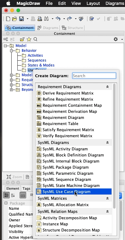
We will start by creating a Use Case diagram under our Use Case package by right clicking on the Use Cases package, Create Diagram and select SysML Use Case Diagram.
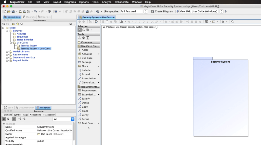
Let’s start creating Use Cases!
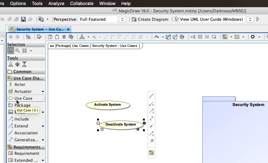
First we will select ‘Use Case’ on the toolbar and click here on the diagram. We’ll name this Activate System. The second one we will create we’ll call Deactivate System.
The third Use Case we’ll call Monitor System.
And since our customer will most likely want a way to monitor the system from a location that’s off-site, we should create a Use Case for Remotely Monitor System.
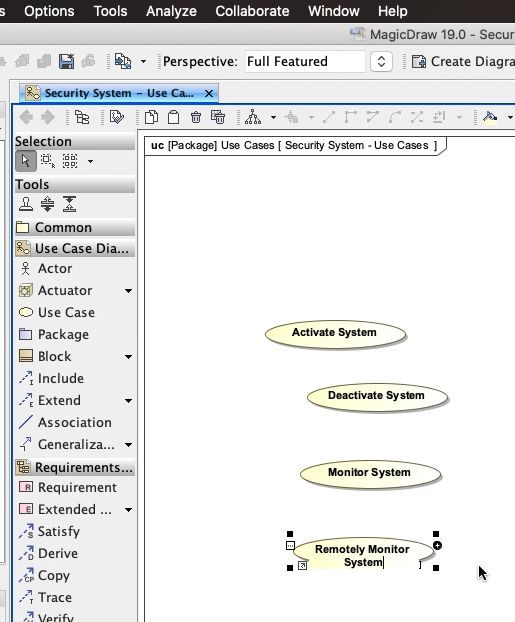
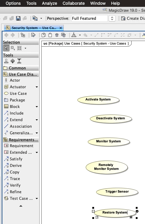
The last two Use Cases will be Trigger Sensor and Restore System.
You’ll notice that we are using Verbs to name these Use Cases which is a Best Practice.
Now let’s create our Actors. We will find our Stakeholders package and right click, Create Element, and select Actor.
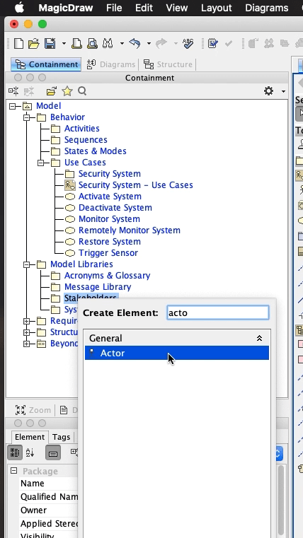
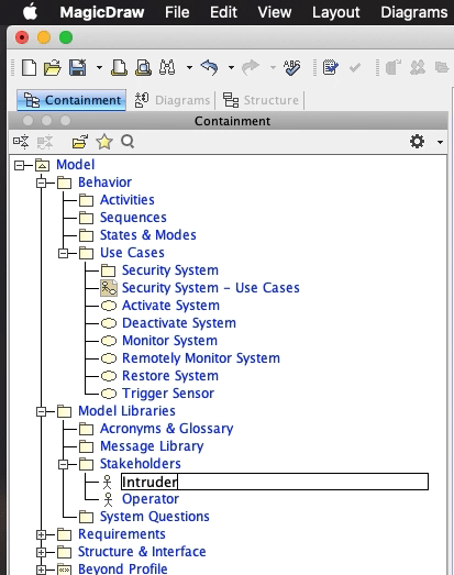
We’ll name this one Operator. The second one will be Intruder.
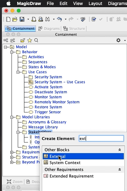
And the third one will actually be an External System called Security Company. So we will use an External System block for this.
Right click on the Stakeholders package, select Create Element, and select External.
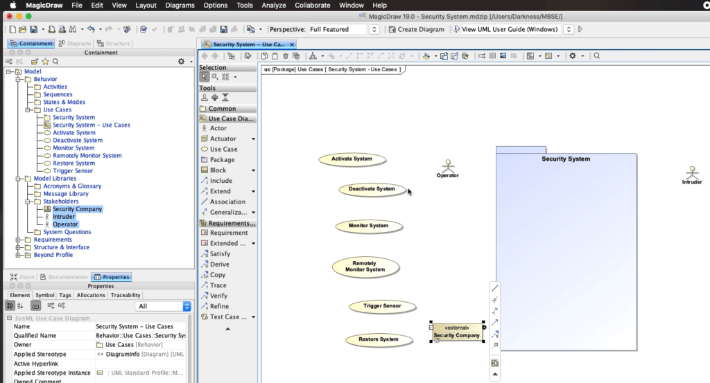
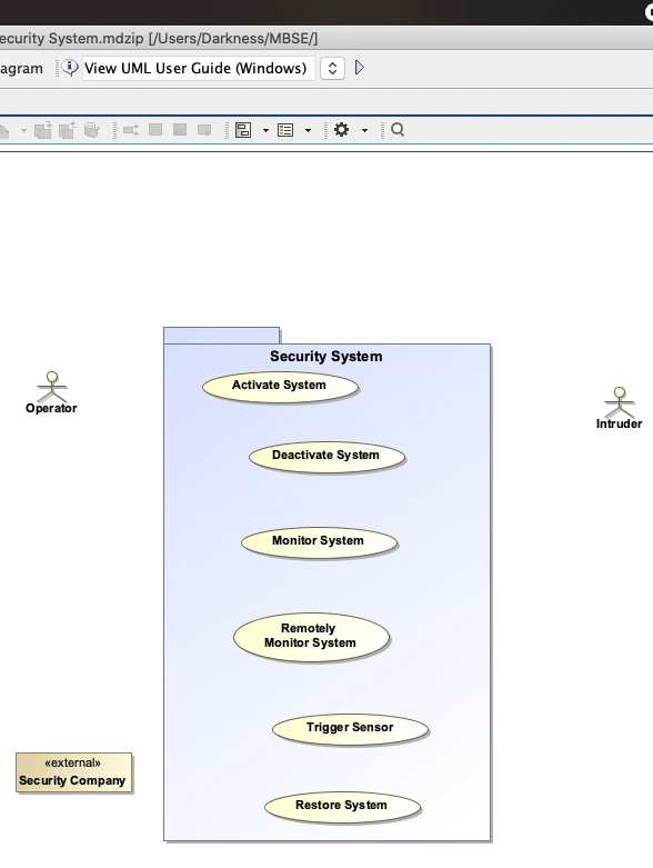
Let’s select all our Use Cases and drag them into our Security System package. This means that the Security System package now owns these Use Cases.
Creating Relationships
We will now begin to create relationships between our Actors and Use Cases.
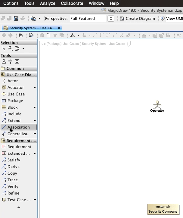
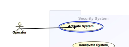
We want to convey that the Operator invokes the Activate System Use Case. So we will create an Association relation between the two.
Click the Association relationship in the toolbar.
Now click on the Operator actor and you should see an Association line extend with your mouse.
Click on the Activate System use case.
There! You created your first Association!
The Operator will likely Deactivate the System as well. So we’ll follow the same process and create an Association from the Operator to Deactivate System.
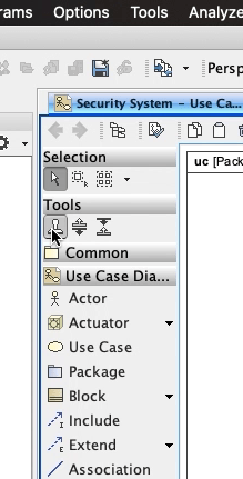
Since we will be creating more of the same type of relationship, we can use the Stamp Tool by clicking the button here and now create our Associations.
Now we need to understand how the Use Cases relate to each other.
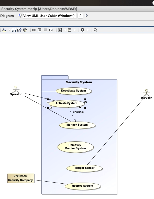
We will start with the Include relationship. We know that the Monitor System Use Case will most likely take place after the Activate System Use Case.
We’ll create an Include starting with Activate System and then to Monitor System.
Let’s think about what are some optional use cases.
Optional Use Cases are functionality that may or may not take place after a base Use Case.
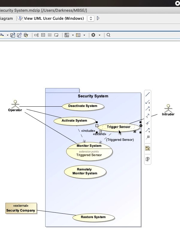
In our case, Trigger Sensor can take place after the Monitor System. So we’ll create an Extend Relationship here. And name our Extension Point: Triggered Sensor.
We’ll add another Extend for Restore System and name the Extension Point: Error Notifications.
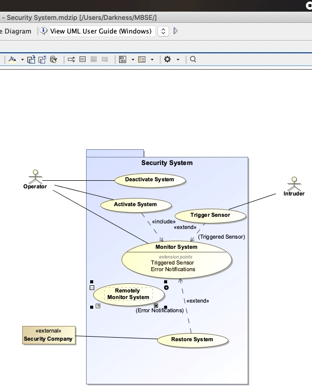
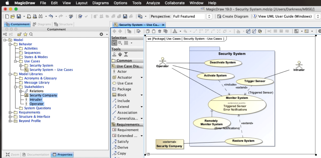
It seems like it would be a subset of the Monitor System Use Case. We can show this relationship by creating a Generalization relation between the two.
Remember that a Generalization Relationship provides a way to specify a variant of a use case.
This means that the Remotely Monitor System Use Case will inherent from the Monitor System Use Case.

Pingback: Creating Use Case Roles - Beyond MBSE
Pingback: Actor - Beyond MBSE