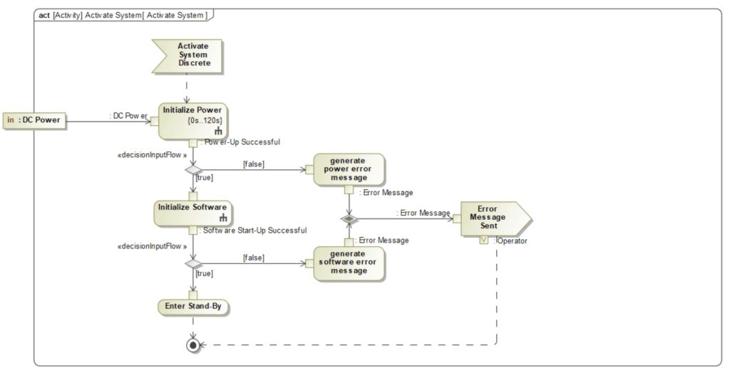
Functions and Activity Diagrams are representations of workflows of stepwise activities and actions with support for choice, iteration and concurrency.
Activity Diagrams are some of the most widely used behavioral diagrams within SysML.
An activity diagram’s main purpose is to help define the functionality of a system.
One of the key applications of using activity diagrams, is to help specify your use case. These diagrams are referred to as use case specifications.
Another key application of these diagrams is to specify internal system behavior.
Functions and Activity Diagrams: Key Elements
Activity diagrams can utilize a wide variety of elements to detail the behavior of a system. Having a solid understanding of these elements will make your life a lot easier and make you fly through the creation of these behavioral diagrams. Think of it like the toolshed: if you understand all of the tools and what they can be used for, you can build things much more efficiently.

Activity
An Activity is the representation of a property or class which messages are interacting between.
Action
An Action is a task to be performed.


Send Signal Action
A Send Signal Action represents an invocation action that creates a signal from its inputs, and transmits it to the specified target object.
Accept Event Action
An Accept Event Action represents an action that waits for a specific event to occur. This action handles asynchronous messages, including asynchronous calls.


Activity Parameter Node
Activity Parameter Nodes are object nodes at the beginning and end of the flows that are used to accept inputs and provide outputs from activities.
Initial Node
An Initial Node portrays the beginning of a set of actions or activities.


Activity Final
An Activity Final will stop all control flows and object flows in an activity (or action).
Flow Final
A Flow Final acts as a sink for control tokens.


Decision Node
A Decision Node waits for an input (control or object) token on its input flow and places it on one outgoing flow based on guards.
Merge Node
A Merge Node waits for an input (control or object) token on any input flows and then places it on the outgoing flow.


Fork
A Fork duplicates input (control or object) tokens from its input flow onto all outgoing flows.
Join
A Join waits for an input (control or object) token on all input.

Functions and Activity Diagrams
Functions and Activity Diagrams: Key Relationships

Control Flow
A Control Flow shows the sequence of execution.
Object Flow
An Object Flow shows the flow of an object from one activity (or action) to another activity (or action).

Functions and Activity Diagrams: Common Applications
Behavioral Analysis
Activity Diagrams are a common analysis tool for understanding and documenting desired system behaviors. Many use this analysis to generate Functional requirements for the system of interest.
Interface Management
Activity Diagrams are a great way to show how system behaviors can induce the exchange of messages and energy. These exchanges map to systems interfaces.
Behaviors within swim lanes provide a means of allocating actions to system components.
Behaviors interacting across swim lanes indicate an interface and interaction between the allocating system components.
Process Flows
Activity diagrams describe processes. These processes include Load Assembly, Packaging or a Maintenance Process.
Mission/Operation Modeling
Activity diagrams tier and decompose system behaviors for large scale missions.


Pingback: Model Organization - Beyond MBSE
Pingback: Activity - Beyond MBSE